The reason I love practical electronics so much is because of its modularity.
You see at a little scale it really gives you an insight into how big structural mechanisms work.
For example, as an engineer, I always wondered how do big mechanical systems like automobiles, airplanes, etc. are developed.
It was later when I worked as a Deputy Manager in a corporate structure did I realize it’s really a matter of individual departments coming together.
You see doesn’t matter how big a structural mechanism is, it is made up of small fundamental structural units.
Electronic subsystems are no different.
A big automated electrical unit comprises small embedded systems working in tandem.
In the upcoming posts, I am going to share some really cool electronics projects that I have been working on.
I urge you to subscribe to the blog so that I can reach out as soon as I publish the post.

There also you will learn that no matter how complex a project is, it can always be broken down into modules that eventually form the bigger project.
Today let me teach you one of the most common projects that anyone who wants to make his or her understanding a little deeper in electronics takes up.
Let’s learn how you can control the speed of a DC motor using Raspberry Pi and L293D IC.
Now, I learned how to control the speed of a DC motor in my college days using Arduino.
If you are an absolute beginner in embedded systems, maybe I will recommend you to learn DC motor speed control using Arduino only.
However, if you are already using a Raspberry Pi in a project, it makes sense to learn how to control the speed of a DC motor with it.
This will also give you an insight into how you can use Raspberry Pi in creative ways.
So, it doesn’t matter whether you are just learning to control the speed of a DC motor using Raspberry Pi or deploying it into a project, I will ensure the article is wholesome and comprehensive to make your understanding total.
A few more related articles to make your understanding more comprehensive(opens in a new tab)
- What is PWM and how to use it in practical electronics?
- Beginners guide to setting up Raspberry Pi
- Can Raspberry Pi be used as a general purpose computer?
- Do arduino sensors work with Raspberry Pi?
- How to send sensor data from arduino to raspberry pi?
Core Operating Principle
So how exactly are we going to control the speed of a DC motor using Raspberry Pi?
In order to achieve the speed control of DC servo, we will be writing some python scripts that are going to get executed on the Raspberry Pi.
The DC motor driver IC or L293D will be connected to the GPIO pins of the Raspberry Pi from where the signals will dictate in which direction the motor is going to run into and with what speed.
Raspberry Pi
I have created a separate post dedicated to properly setting up Raspberry Pi for practical electronics here.
If you are an absolute beginner when it comes to Raspberry Pi I highly recommend reading the post. It will put you up to speed with Raspberry Pi.
Here is the TL;DR version though,
A Raspberry Pi is a credit card size computing unit that in addition to having all hardware units required to make a functioning computer also has what are known as GPIO pins for real-time interaction with the external world.
You can easily program the GPIO pins to interact with external hardware, which is what we are going to do in order to control the speed of a DC motor.
Using Motor Driver L293D
The output signals that are going to be generated from Raspberry Pi via GPIO pins are going to be transferred to the motor driver IC L293D.
L293D is nothing but an intermediate IC that is used to control DC motors. It is a small current amplifier that takes a low-current control signal from the Raspberry Pi and converts it into a corresponding high-current signal that can drive a motor.
Because we are using Raspberry Pi to control the speed of our DC motor, we will be creating our executable script using Python.
People who are already well versed with Python or any programming language like JavaScript or C++ will find how easy everything is.
For people who are beginners with practical electronics or coding, you don’t need to worry.
All the commands that we are going to use are easy enough to understand and execute. Additionally, wherever necessary I will leave comments that will make it easy for you to understand what exactly are we trying to achieve through that particular code.
Pulse Width Modulation
Now that we have some clarity of what the hardware units are going to do let me address how exactly are we going to control the speed of a DC motor.
In order to control the speed of a DC motor, we are going to use what is called Pulse Width Modulation.
In simple terms, PWM means that we are going to control for what duration the voltage is high on any particular pin.
The time for which the signal remains at high is called the duty cycle and it will dictate what percentage of power is being applied to the motor.
Thus, this will in a non-resistive or without any kind of power dissipation will control the speed of a DC motor.
The gif below will give you a visual depiction of what PWM actually is.
I have dedicated one complete article towards learning exactly what PWM is, check it out here.
If you are an experienced electronics enthusiast, I am fairly sure you know all about PWM.
But if you are a beginner I highly recommend you learn about PWM in as much detail as you can. Start from here.
So how exactly are we going to implement PWM on L293D?
Have a look at the pin diagram for L293D.
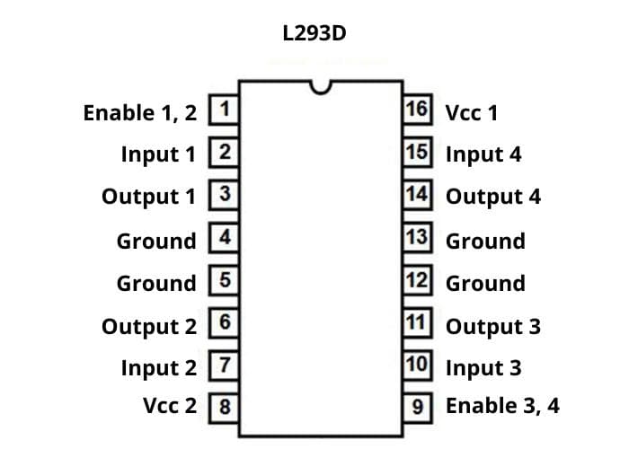
As you can see L293D uses a pair of inputs to relay the direction of outputs.
In addition, it also has an enable pin or the master control pin which when set to high enables all the pins to the left of the IC. Similarly, pin 9 or enable pin 3,4 when set to high enables the operation of the right side of the IC.
We will use it to generate PWM which you will see in a second.
Now in order to move the motor forward, enable pin needs to be on high and we need to provide a high signal to input 1 and low at input 2.
On a similar basis, if you need to move the motor backward, with enable on, provide low to input 1 and high on input 2.
If you provide high or lows simultaneously to both the inputs, the motor won’t run.
Now, what about controlling the speed of the DC motor?
As explained PWM is the non-resistive method of controlling the speed. So, what do you feel is the way to go?
The first thought that should come to your mind is by providing pulse width modulated signal to the input pins the speed control of the servo can be achieved.
Well, yes, but the thing is the whole process will be3come too complicated.
How’s this for a solution.
Because the IC contains enable pins to control it’s on and off state, we can set the input pins to ensure the motor is running and provide a modulated signal at the enable pin.
On doing this the L293D IC will only provide power corresponding to the duty cycle, its enable pin is subjected to.
This simplifies our code and ensure less room for mistakes.
In order to accomplish this whole process, we will need 3 GPIO pins from Raspberry Pi, one 3.3 V power pin, and one pin that can be pulled to the common ground.
2 of the 3 GPIO pins will be used to select which direction will the motor move and the remaining one will be used to control the speed via the enable pin.
Hardware Configuration
So, that was the overall principle this project will work upon.
I hope I was able to give you a comprehensive outlook or the overall picture of how we are going to accomplish the task of controlling the speed of a DC servo.
Now it’s time to connect all the required hardware together to accomplish the task.
Connecting everything together is pretty easy and intuitive actually.
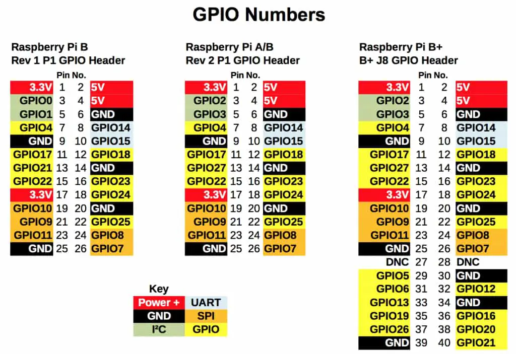
Let me share with you the pin diagram of a Raspberry Pi.
Here is exactly how you go about doing it.
If you observe the pin diagram of our motor driver IC, it shows that it receives two power inputs, VSS(3.3V)and Vs(12V).
This is because while the IC operates at TTL level by using 3.3 V and 20mA, the motor operates at a much higher voltage level and current, 12V and 9V, 400mA.
The higher voltage gets routed via an external battery as shown in the circuit diagram to the motors.
Now you understand why you need an intermediate driver like an L293D because normal circuitry operates at TTL, 3.3V to 5V and you need more voltage and current levels to operate more power-hungry devices.
- Important Note: Never do the mistake of extracting more power from a device than what it is rated for. This can very well damage the connected hardware. Be very mindful of what are the requirements of individual ICs and circuits.
When I start making connections, I adopt the small to big approach.
It’s just a personal thing, I choose a simple reference from where I start making all my connections. And then proceed to arrange my other bigger hardware components around it to make things simple.
It’s completely up to you how you approach it. I just find this approach easier and, in my experience, I make fewer connection mistakes this way.
In this case, for example, I am choosing the L293D as my starting point.
Place the L293D on your breadboard and immediately pick five jumper wires that you are going to connect to VSS, Enable 1, Input1, Input2, and ground.
Now you will be able to see five wires waiting to get connected to its other destination.
- Connect the Vss to the 3.3V power supply from Raspberry Pi, or pin 1 (refer GPIO pin diagram above).
- Next up connect the GND pin from L293D to the GND of Rpi, which is pin #6.
- Connect the Input 1 jumper to GPIO2 or pin 3 of Rpi and Input 2 jumper to GPIO3 or pin 5 of Rpi.
- And to provide the necessary PWM signal, connect the Enable 1 pin to GPIO4 or pin 7 of the Rpi.
And we are almost there. If you were able to connect all of these connections neatly you have completed half of all the required connections and not to mention the tricky ones.
Now let’s go ahead and connect the remaining ones.
- Take a 9V battery and connect its positive side to the Vs and negative to the common ground.
- Next connect the two ends of your motor to the outputs of the L293D IC and that is it.
That wasn’t too complicated now, was it.
I hope you understand the importance of understanding the core operating principle first.
If you have the basic concept clear in your mind, all that is left next is to see the pin diagram of the circuitry involved and make the connection.
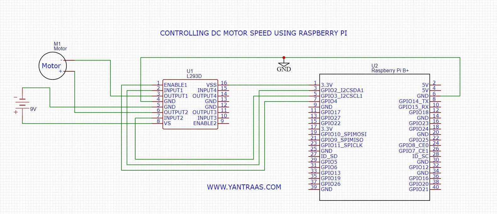
Here is a schematic of the completed circuit, to put everything into perspective.
Software Setup and Code
Finally, after understanding the core principle and hardware setup for the project, it’s time to write the code that will make everything work the way we want it to.
In order to make the post useful for the masses, I am not going to make the code too complex.
I will make you understand which command does what and how to modulate the command to your particular need.
We will be writing all our code in IDLE2. To open IDLE 2, click on menu, then click on programming and select Python 2(IDLE).
In the text editor that opens up, start writing your code.
- First and foremost, you need to import the GPIO module using import command to activate the GPIO pins.
import RPi.GPIO as GPIO- In order to introduce some delays when switching motor directions or PWM duty cycle we need to also import sleep command.
from time import sleep- Now let’s initialize the GPIO pins into board mode so that you can access them via their pin numbers as indicated in the pin diagram above. Use this command to do so.
GPIO.setmode(GPIO.BOARD)- Next let’s setup the pins that we discussed above as outputs.
GPIO.setup(03, GPIO.OUT)
GPIO.setup(05, GPIO.OUT)
GPIO.setup(07, GPIO.OUT)- Let’s latch a variable p with the PWM values of the dedicated PWM GPIO pin
p=GPIO.PWM(07,100)- Now start the pulse width modulation with 0% duty cycle so that the enable pin doesn’t receive any signal yet.
p.start(0)These were the general initialization commands that are going to be common for everyone who is working on this project.
From here on the code will change depending upon what you want to do with the whole setup.
For example, if you want to create a PWM demo setup where the speed of your motor first increases then remains constant, and then decreases over time you can do so.
If you want the same to happen at the press of a button you do so too, but you will have to change the hardware setup a little bit.
You will have to connect two DPDT switches to two other GPIO pins which will act as inputs and change the code accordingly.
The possibilities are virtually endless and will depend on your need.
Here I will create a simple code where the motor will run in forward direction at 25% power for 5 seconds and then the motor will run backwards at 50% duty cycle for another 5 seconds.
You can change any of these values as per your convenience.
- Setting the motor to run in forward direction
GPIO.output(03, True)
GPIO.output(05, False)- Providing a 25% duty cycle at the enable pin,
p.ChangeDutyCycle(25)- Start sending the signal to the enable pin via GPIO pin 7
GPIO.output(07, True)- Holding further code execution for 5 seconds
sleep(5)- Turn off the enable pin to begin the process in other direction
GPIO.output(07, False)- Reverse the direction of the motor
GPIO.output(03, False)
GPIO.output(05, True)- Changing the duty cycle to 50% so that the motor now operates in the other direction at 50% power.
p.ChangeDutyCycle(50)- Reinitialize the enable pin
GPIO.output(07, True)- Hold further code execution for another 5 seconds
sleep(5)- Turn the enable pin OFF again
GPIO.output(07, False)- Finally let’s stop the pulse OFF and clean and reset the GPIO channels
p.stop()
GPIO.cleanup()
If you did everything correctly you will see that your motor first runs in the forward direction at a slow speed for 5 seconds and after that, it will run in the opposite direction for another five seconds.
I know the code is simple but if you are a beginner I highly recommend starting with this code only so that you have a grasp of what is going on.
If you run this code successfully go as creative as you can.
You can vary the duty cycle by using a variable that changes its value on every loop so that your motor speed increases successively as you watch it.
You can apply the same procedure in reverse to see the motor speed get reduced.
If you are feeling particularly wide you can even modulate the signal on the basis of signals received from an actual analog sensor.
You can learn all about how to interface an analog sensor with Raspberry Pi here.
And in that direction, I think this article on how to send sensor data from Arduino to Raspberry Pi will help as well.
You see once the core concepts are grasped you will be limited by your imagination only.
Raspberry Pi FAQs
I hope I was able to relay a lot of clarity on the topic of controlling DC motors using Raspberry Pi.
I very well understand that no knowledge is complete. And no matter how thorough I am with my write-up, there will still be some pieces that I won’t be able to relay to everyone who is reading this post.
And therefore, I am leaving this FAQ section below which I will keep on updating depending on whether I find some good questions related to the topic that will be a good fit.
So, if you have any questions leave them in the comments below and who knows maybe I will feature them in this section with your personal profile link on it.
Can Raspberry Pi Control Motors Directly?
No, you should never connect a motor directly with your Raspberry Pi. This can very well lead to the damage of your Raspberry Pi and other connected circuit elements. The power requirements to operate a motor is very high compared to the TTL level at which Rpi operates. Therefore, you need a motor driver IC like the L293D that reroutes more power from an external battery to match the motor’s power requirements.
How Many DC motors can a Raspberry Pi Control?
Directly, Zero. Never try to directly operate a motor by connecting it to Rpi’s GPIO pins. Using external motor driver ICs and motor controller boards, how many motors you can control with Rpi will depend upon how many extensions can you provide to a Rpi’s capability.
Can You Use L298N With Raspberry Pi to Control a DC motor?
Yes, you can use L298N as the motor driver IC to operate and control DC motors. L293D and L298N do obviously have differences at the specifications level but operationally you can use both to achieve the same goal. The only thing you need to be mindful of is which of the two will match the specification criteria the circuit is asking for.
I hope this article on how to control the speed of a DC motor using Raspberry Pi and L293D was able to provide you comprehensive knowledge and insight into the topic.
I have made this article in such a way that it will appeal to both beginners and Saiyan geeks :P.
But if you still feel there are some gaps that still remain in your understanding do feel free to relay it down in the comments below.
If you liked what you read till now. Please don’t go away without subscribing to the blog. I like connecting with people who enjoy tech and who want to use it to learn something new, or enhancing their productivity, or building something beautiful using it.
An in that direction this blog contains golden nuggets I am fairly sure you won’t find anywhere on the planet.
Here is the window you need to subscribe to the blog. 😊
I will see you inside.
Take great care of yourselves and I will see you in the next one.
Bbye 😊